
01 / The challenge
Find the mechanical cause of the vibration.
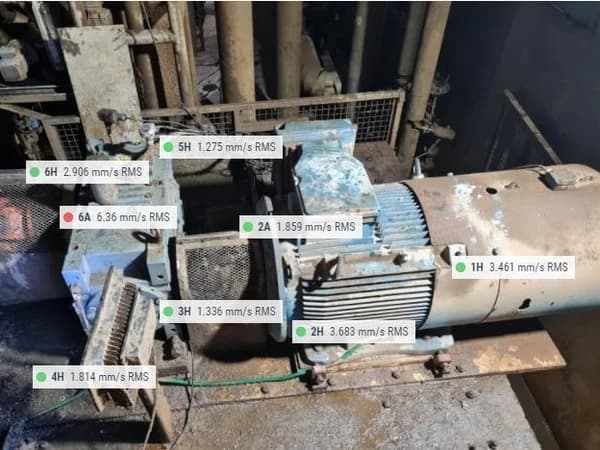
A paper mill needed to investigate abnormal vibration in a fixed-speed machine. Measurements across the drive showed different vibration levels, with one point standing out from the surrounding readings. The question was which mechanical condition required attention.
Temporary monitoring gave the assessment a defined focus. A Twave T8-L system and accelerometers recorded the vibration, with a load input included in the setup. The investigation identified two faults to address: misalignment and structural looseness.
02 / The approach
Connect the diagnosis to specific corrective work.
Measure the abnormal vibration
A temporary T8-L Turbomachinery installation collected vibration measurements using accelerometers. The setup also included a static load input. The equipment photograph identifies measurement points across the drive and shows where the higher vibration occurred.
Identify the mechanical faults
The assessment identified misalignment and structural looseness. These findings directed the work toward the alignment of the machinery and the security of its mechanical connections.
Correct and measure again
Precision alignment and bolt tightening addressed the diagnosed faults. The follow-up vibration reading provided a direct check of the machine's response to that work.
03 / The documented outcome
Vibration fell after alignment and bolt tightening.
The initial overall vibration-velocity gauge showed 6.356 mm/s RMS, while the equipment photograph marks point 6A at the rounded value of 6.36 mm/s RMS. Following precision alignment and bolt tightening, the final readout for point 6A showed 1.114 mm/s RMS.
Both values are vibration velocity in millimetres per second, expressed as root mean square, or RMS. Keeping the same measurement type and units makes the before-and-after change clear.
- Before correction
- 6.356 mm/s RMS
- After correction
- 1.114 mm/s RMS
- Faults identified
- Misalignment and structural looseness
- Corrective work
- Precision alignment and bolt tightening
04 / Applying the findings
Include verification in the alignment job.
For another machine, start with the vibration history, operating speed and load, recent maintenance and the condition of the supports and connections. A vibration monitoring assessment should identify the likely fault and the evidence needed to choose the corrective work.
When misalignment and looseness occur together, define the work for both conditions. An alignment service should include a clear measurement plan before and after correction. Record where and how the readings are taken, together with the operating conditions, so the comparison can be interpreted.
Use the post-work result as the starting point for follow-up monitoring. The sampling interval should fit how quickly the fault can develop and how the machine can be accessed. Our guide to monitoring between routine vibration rounds explains that decision for machines where conditions change quickly.