A reciprocating compressor returns to the maintenance list, yet the overall vibration reading has not explained the problem. The team may need a better view of cylinder operation and the events within each stroke.
Reciprocating compressor monitoring should start with the component and operating question. Discuss cylinder pressure, cycle timing, temperature, vibration and relevant position or process measurements according to the machine and suspected concern. Select portable or online collection around how the equipment operates and how quickly the team needs evidence.
The aim is to connect the finding to a specific part of the compressor and a check that can confirm the explanation. More channels are useful only when the measurements support a decision.
Define the question for each part of the machine
Begin with the compressor configuration and duty. Identify the stages, cylinders, loading arrangement, gas conditions, speed and recent work. State whether the concern is reduced performance, repeated valve attention, an abnormal mechanical event or another documented symptom.
Use those questions to prepare a component-by-component scope with the analyst. Cylinder-performance evidence concerns what the gas and valves do during compression. Mechanical measurements concern the motion and impacts of the machine. Process conditions explain the duty under which those observations occurred.
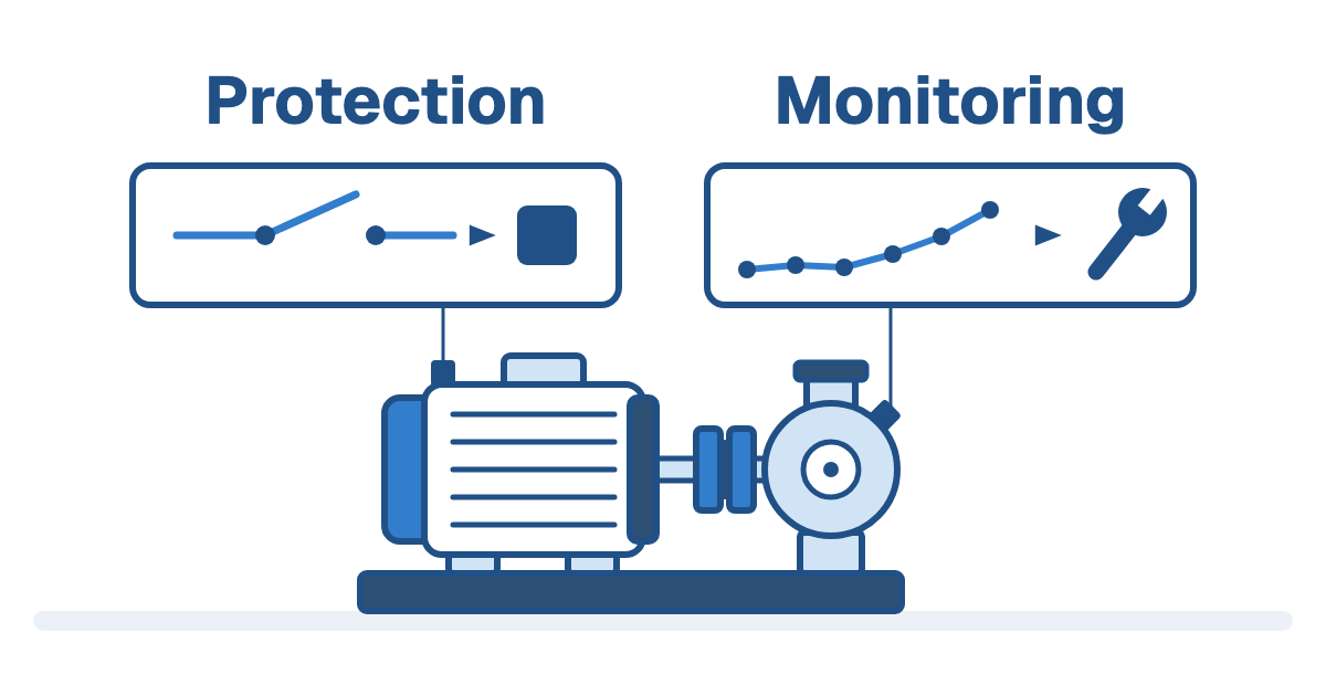
Keep the existing machine-protection arrangement in the scope. A diagnostic assessment and a protection function serve different operating decisions. Do not assume a portable assessment or a condition dashboard replaces the site's protection system.
Why pressure and cycle timing belong together
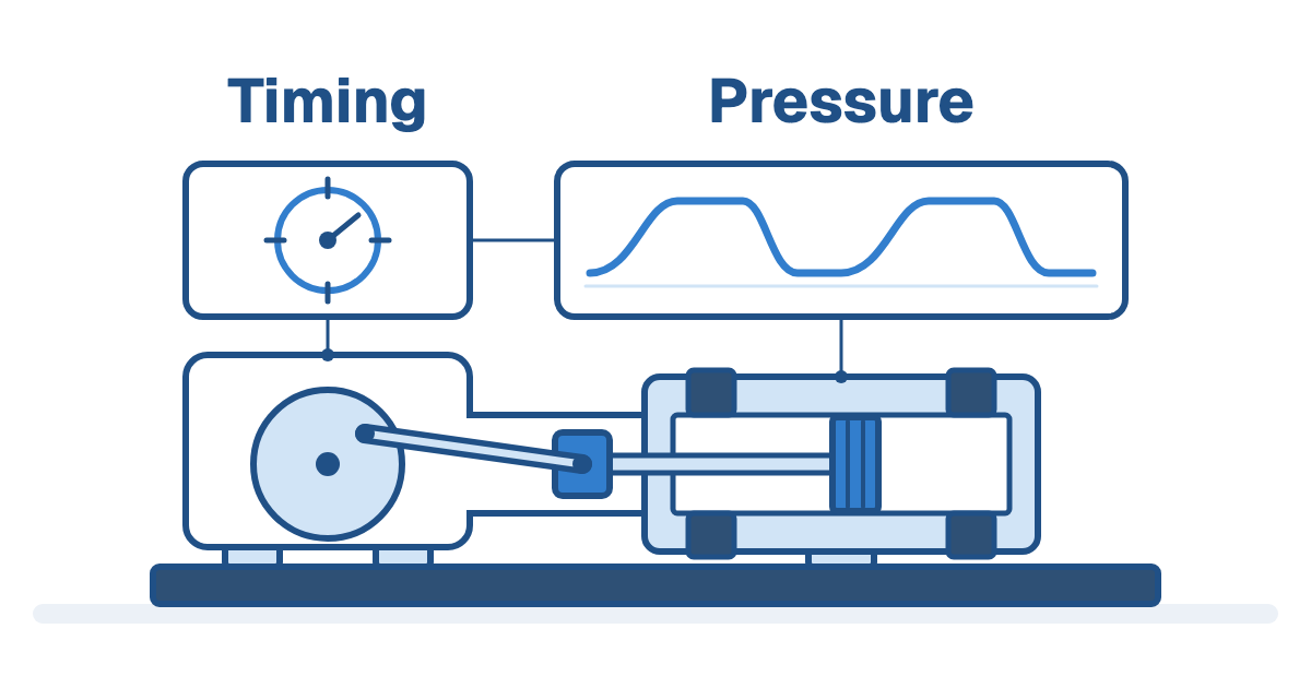
Dynamic pressure follows pressure changes through the compressor cycle. A crank-angle reference identifies the position in that cycle. Viewed together, the records help an analyst compare pressure behaviour and the timing of events rather than reducing the machine to a single overall number.
This gives the investigation a more specific question. Does a pressure pattern differ from a suitable reference? At what part of the cycle does an impact occur? Which operating state produced the observation? The answer depends on suitable acquisition, configuration and interpretation.
Pressure evidence still needs supporting context. Loading, gas conditions and the machine arrangement belong beside the plots. A changed curve is an observation to explain, not a universal instruction to replace a valve.
Use supporting measurements to narrow the cause
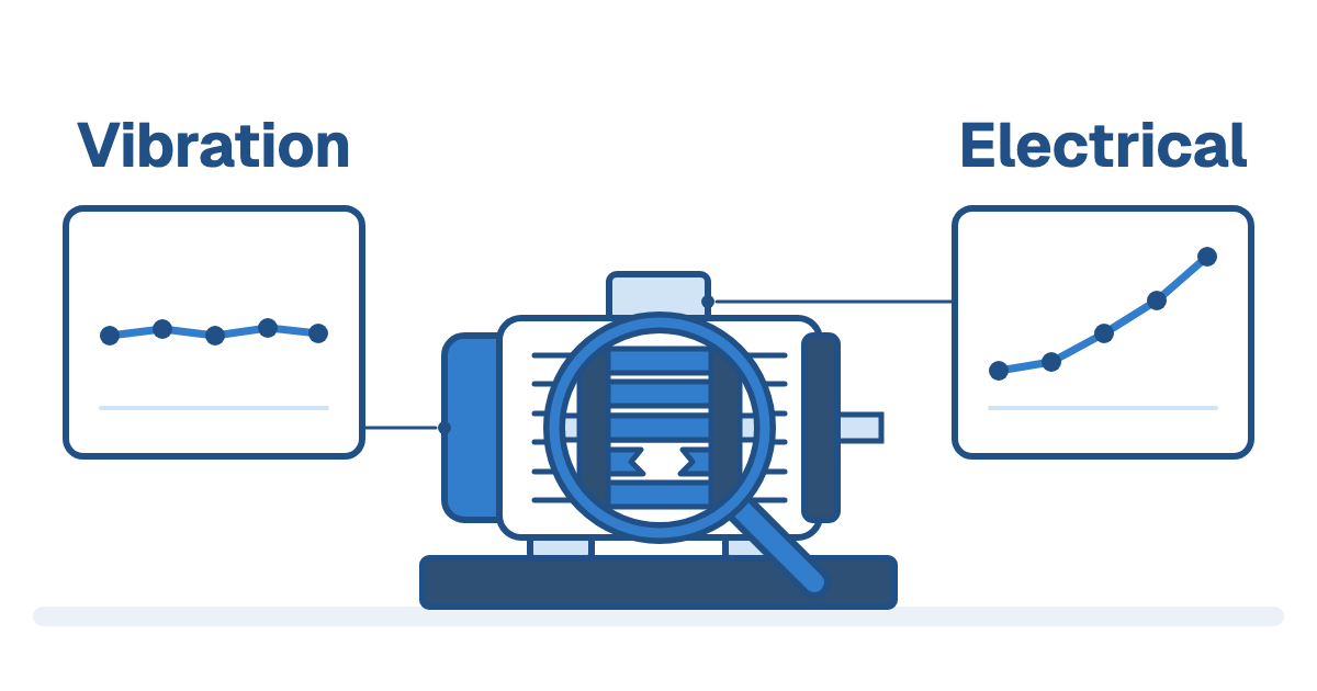
Choose vibration locations and signal views around the suspected component. A record at the frame and a cycle-related record at a crosshead or cylinder may provide different information. Ask the analyst why each location and method belongs in the scope.
Bently Nevada's published compressor guidance discusses cylinder vibration and cycle timing, and its valve-leakage example combines pressure-pattern evidence with a temperature comparison to narrow the suspected leak route. The lesson is the diagnostic sequence. Several plausible causes can share an initial indication.
Temperature and process records can help decide what to investigate next. Position measurements may also be relevant to specific mechanical questions. These measurements do not form a compulsory universal package; choose them for the compressor configuration and the question the team needs answered.
What the Resonance Systems evidence adds
NATCOM's oil-and-gas portfolio identifies Resonance Systems for reciprocating machinery. The partner's current portable-kit page describes collecting thermodynamic, vibration and operating data for engines and compressors.
The page explicitly lists dynamic pressure, temperature, ultrasonic, vibration, speed and voltage data. It also describes a handheld analyzer working with Rmonix analysis software. This supports a discussion about combining measurements; it does not establish a fault-detection rate or a guaranteed diagnosis on every compressor.
Resonance Systems states that portable collection can operate without an internet connection, while some update or cloud-storage functions may need connectivity. Confirm the selected sensors, acquisition arrangement, software functions and site requirements before specifying an installation.
Choose portable or online collection around the decision
Portable assessment can support a planned route or a focused investigation when the relevant operating condition can be captured. Agree the points, duty, collection procedure and comparison record so later assessments remain useful.
Online collection is worth discussing where the team needs observations between visits, where the relevant event is intermittent or where asset criticality demands closer observation. Decide what will be recorded, what constitutes an investigation trigger and who will respond.
The choice should include access, available connections, operating changes and analysis capacity. A monitoring system that produces findings nobody reviews leaves the maintenance question unresolved. Conversely, installing permanent hardware before defining the diagnostic scope can create data that misses the original concern.
Prepare the enquiry and the follow-up
Bring the compressor arrangement, operating conditions, recent maintenance and existing protection details. Include prior pressure, temperature or vibration records with their measurement points and timestamps. State the symptom and the maintenance decision currently under consideration.
Ask how the proposed assessment will distinguish the suspected causes and how the team will verify any intervention. Compare follow-up evidence under appropriate operating conditions rather than declaring success from one quieter run.
Explore reciprocating machinery analyzers with NATCOM to discuss a scope built around those questions. For the wider role of measurement trends and continuous observation, the online vibration monitoring guide provides related context.

Frequently asked questions
No single measurement answers every component or performance question. Define the suspected concern and discuss suitable pressure, timing, vibration, temperature and other evidence for the compressor.
The timing reference relates pressure changes to the compressor cycle. It helps an analyst compare operating events and pressure behaviour with a suitable reference under known conditions.
The current partner page lists dynamic pressure, temperature, ultrasonic, vibration, speed and voltage data for reciprocating machinery. Confirm the selected sensors, configuration and required analysis functions for your asset.
Choose around criticality, the operating conditions to capture, access and how soon the team needs evidence. Portable assessment suits defined visits; online collection can supply observations between visits. Agree who will review and act on findings.
Do not assume so. Diagnostic assessment and machine protection support different operating decisions. Define the existing protection arrangement and any proposed change with the responsible site team.