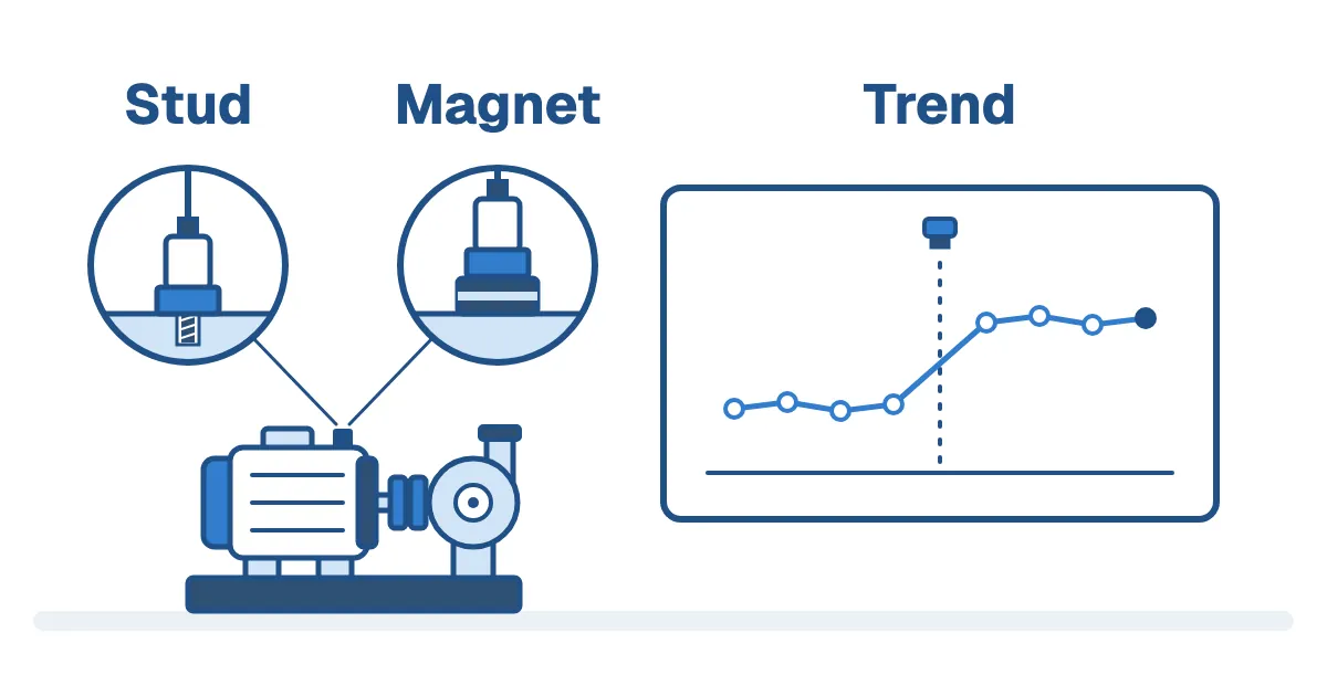
A pump's vibration trend steps upward after a new sensor is fitted. The machine may have changed, but the measurement arrangement changed too. Before recommending a repair, compare the mounting, location, direction and collection settings with the earlier readings.
A vibration sensor measures motion through its connection to the machine. That connection affects what reaches the sensor, especially at higher frequencies. A reading taken with a different mount should therefore carry a clear change record, rather than quietly extending an old trend as though the setup were identical.
This is a measurement-quality check, not a reason to dismiss a warning. If the machine has concerning symptoms, investigate them while establishing whether the new and old data can support the comparison being made.
The mount is part of the measurement
PCB Piezotronics explains that direct stud mounting to a smooth surface gives its accelerometers the broadest usable frequency range. Added mounting mass and softer interfaces can change the response. The applicable limit belongs to the sensor and mounting combination, rather than the sensor specification considered on its own.
That matters when the diagnostic question depends on information beyond an overall vibration value. Ask whether the installed mount supports the frequency range the analyst intends to use. Do not assume that a convenient mounting accessory preserves every capability shown on the sensor's data sheet.
The manufacturer should define the installation requirements. Torque, surface preparation, adhesive selection and adapter suitability are product-specific matters. A general article cannot supply one installation recipe for every industrial sensor.
Check the contact before replacing the sensor
PCB's guidance calls for a smooth, flat contact surface and checking for material that interferes with contact. Use those requirements when inspecting a changed installation. A photograph of the sensor's outer housing alone may not show what is happening at the mounting interface.
For a portable route, record how the sensor is located and oriented at the measurement point. If the method uses a magnetic base, establish the approved surface and placement so the next technician can repeat it. Marking a location only as pump bearing may leave too much room for variation.
For a permanent installation, retain the mount and adapter details alongside the sensor identity. When maintenance removes or refits it, record that intervention. The next analyst needs to know whether a step in the trend coincided with a physical change to the measurement.
Use the location specified for the application
The Schaeffler OPTIME brochure illustrates why sensor placement deserves an engineering decision. Its application table distinguishes mounting locations and sensor arrangements for motors, pumps, fans and gear motors. Its technical table specifies single-bolt M6 mounting, with adapters available.
Those details apply to that product family. They are not permission to put every sensor on the same motor foot or bearing housing. Their value is that the supplier treats the connection and location as part of the application, rather than leaving them to whichever surface is easiest to reach.
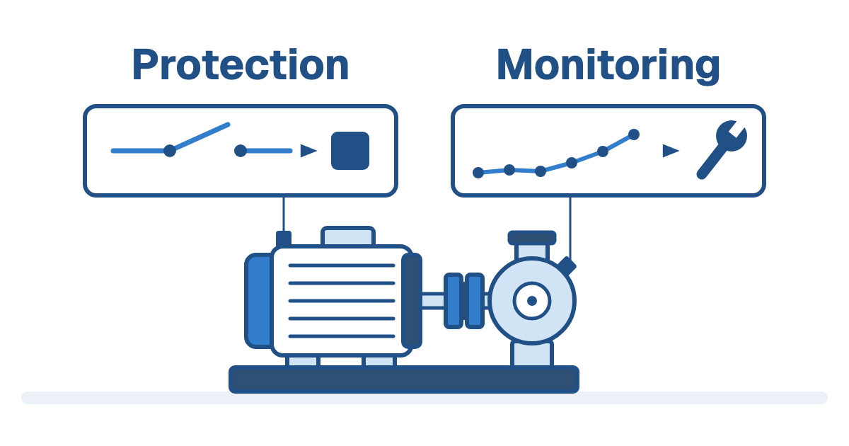
Ask the supplier to mark the proposed locations on photographs or a machine drawing and explain what each location is intended to observe. This is particularly useful when a motor and driven machine have separate concerns. The pump and motor monitoring case shows why component-specific interpretation matters.
Compare like measurements before comparing diagnoses
Suppose a portable reading and a permanently installed sensor disagree. Assemble the records before deciding which instrument is wrong. Compare time, machine speed and load, position, measurement direction, mount, units and collection settings.
The methods may be observing different conditions or reporting different quantities. An overall value and a selected frequency band are not interchangeable simply because both appear on a vibration dashboard. Have the analyst explain the relevant comparison and retain the underlying data where available.
If the mounting arrangement has materially changed, decide how to preserve the old history and establish a documented new baseline. That is an interpretation task. Do not erase the earlier readings or reset an alarm merely to make the plot look consistent.
Make installation evidence part of the monitoring scope
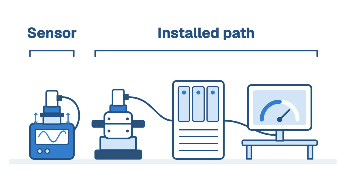
Before fitting a sensor population, request a location schedule, mounting specification, installation photographs and a commissioning record. Include the sensor model, adapter, direction and collection configuration. Agree who reviews the first data and how installation questions are resolved.
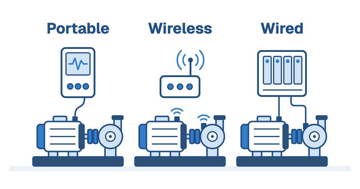
The monitoring-method comparison helps choose portable, wireless or wired collection. Once that choice is made, the physical installation still needs to support the intended diagnostic question.
Start with the machine whose trend is disputed. Reconstruct its measurement arrangement and identify exactly what changed. That may strengthen the case for a developing fault, or it may show that a mounting correction and a new baseline are needed before the trend can support a maintenance decision.

Frequently asked questions
Yes. Mounting accessories can alter the sensor system response. Check the usable frequency range and installation requirements for the actual sensor and mount combination.
Choose the method that meets the measurement requirement and the sensor manufacturer's installation guidance. Access and portability matter, but the selected arrangement must still support the intended measurement.
Record the new position, direction and mounting details, then have the analyst decide how the data can be compared. A different setup should not silently extend the earlier baseline.
No. Calibration evidence has a defined test scope. It does not establish that the machine location, mounting connection or monitoring configuration is suitable.